


Introduction to the flange product
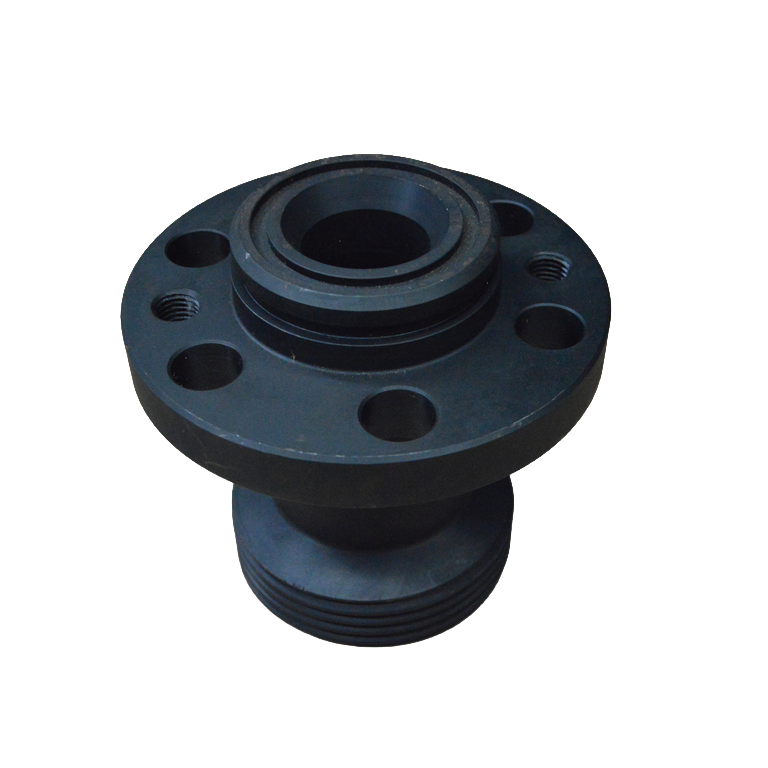
The discharge flange is a pressure-bearing connection accessory in the hydraulic end discharge system of the plunger pump. It is usually installed at the hydraulic end discharge port position and is used to connect the discharge main pipe, high-pressure discharge pipeline or corresponding connection components, to transport the high-pressure medium discharged from the working chamber of the plunger pump to the downstream system.
After the plunger completes its compression stroke, the pressure inside the working chamber rises and pushes the discharge valve to open. The medium then passes through the discharge valve and the internal discharge channel at the hydraulic end into the discharge side pipeline. The discharge flange is located in this high-pressure medium conveying connection system and needs to maintain a reliable mechanical connection and sealing fit between the hydraulic end and the external discharge pipeline.
The flange itself is usually a metal load-bearing connection component. The actual sealing function to prevent leakage at the mating surface generally needs to be accomplished in combination with flange sealing rings, gaskets, O-rings or other special sealing structures. The specific sealing form should be based on the corresponding pump type and the original flange structure.
The main function of the discharge flange
1. Connect the hydraulic end discharge port: The discharge flange is matched with the hydraulic end discharge interface to form a connection channel for high-pressure medium to enter the discharge pipeline from the pump cavity.
2. Connect the main discharge pipe or high-pressure pipeline: Reliably connect the discharge end of the plunger pump to the subsequent pipeline through flange holes, bolts or studs and other connection structures.
3. Provide a sealing installation foundation: The flange sealing surface or sealing groove offers installation and clamping positions for flange sealing rings, O-rings, sealing gaskets and other components, enabling a reliable static seal to be formed at the connection points.
4. Maintain the position of the pipe interface: The discharge flange passes through the center hole, installation surface, bolt holes and other structures to ensure the correct axial and radial assembly relationship between the hydraulic end and the discharge pipe.
Working characteristics of the discharge side
Compared with the common low-pressure pipeline flange, the specific structure of the discharge flange needs to match the working conditions on the discharge side of the plunger pump. The medium discharged by the plunger pump has obvious periodic pressure changes. The discharge connection part needs to withstand the corresponding internal pressure action, bolt preload, as well as pressure pulsation and pipeline load during operation.
Therefore, the flange thickness, connection hole arrangement, sealing structure, material and fastening requirements of the discharge flange cannot be determined separately from the specific pump type. When replacing, it should be matched in accordance with the original hydraulic end interface and discharge system design.
Flow channels and paths
The central flow channel of the discharge flange is an important passage for high-pressure media to pass through. The central diameter and internal transition structure of it need to match the hydraulic end discharge port and the downstream pipeline.
If the effective diameter of the replaced flange is significantly smaller than the original design, it may increase the local flow resistance. If the internal orifices, steps or transition positions are inconsistent with the original structure, it may also affect assembly and sealing.
Therefore, when selecting the model, it is not only necessary to check the outer diameter of the flange and the bolt holes, but also to confirm the center diameter, internal steps and the dimensions of the interfaces on both sides simultaneously.
Flange holes and installation dimensions
The number of installation holes, hole diameters, hole center circles or hole center distances of the discharge flange must be consistent with those of the hydraulic end and the matching connecting parts.
Even if two flanges have similar outer diameters and center diameters, they still cannot be directly interchanged if the number of bolt holes, hole spacing, installation thickness or sealing surface structure are different.
For the discharge flanges with directional requirements, the layout of the installation holes, the direction of the flow channels and the spatial positions of adjacent components should also be checked to avoid misalignment of the pipeline direction or connection interference after assembly.
The fit relationship with flange sealing
The discharge flange and the flange seal belong to different parts in the same connection assembly.
Discharge flange: It is the pressure-bearing and connecting main body, responsible for connecting the hydraulic end with the discharge pipeline, and providing an installation surface or sealing groove for the sealing parts.
Flange sealing: It is a sealing element installed on the flange mating surface or in the sealing groove, mainly responsible for preventing high-pressure media from leaking from the mating surface.
When replacing the discharge flange, the matching sealing parts and sealing grooves should be inspected simultaneously. If the original sealing parts have undergone compression deformation, damage or do not meet the requirements for reuse, they should be replaced in accordance with the equipment maintenance requirements.
Common failures and inspection sites
When conducting maintenance on the flange, special attention should be paid to inspecting the flange sealing surface, sealing groove, center flow channel, bolt holes, installation surface and structural transition positions.
Common abnormalities include scratches or erosion on the sealing surface, corrosion of the sealing groove, damage to the bolt hole, indentations on the installation surface, flange deformation, and erosion of the flow channel, etc.
If leakage occurs repeatedly at the flange connection position, it is not only necessary to repeatedly tighten the bolts, but also to check whether the flange sealing surface is flat, whether the sealing groove is damaged, whether the specifications of the sealing parts are correct, and whether the pre-tightening of each fastener is uniform.
Key points for selection
When purchasing the flange for the plunger pump, it is recommended to focus on confirming the following information:
1. Brand, series and specific model of plunger pump;
2. Hydraulic end or pump head model;
3. The specific installation position of the discharge flange;
4. Central diameter and internal flow channel dimensions;
5. Flange outer diameter and overall thickness;
6. Number and diameter of installation holes;
7. Center circle of the hole or center distance of the installation hole;
8. Sealing surface and sealing groove structure;
9. Specifications of matching sealing parts and fasteners;
10. Original part number, physical sample or technical drawing.
Installation and Maintenance
Before installation, the central flow channel of the flange, the installation surface, the sealing surface and the sealing groove should be cleaned and discharged to ensure that there are no metal debris, old sealing materials, burrs or other foreign objects that may affect assembly.
When installing, it is necessary to ensure that the discharge flange is correctly centered with the hydraulic end and the pipeline interface. It is not advisable to correct obvious pipeline misalignment by forcibly tightening the flange bolts, as this may cause the flange and the hydraulic end interface to bear additional pipeline stress.
The multi-bolt connection structure should be tightened step by step and evenly in accordance with the requirements of the corresponding equipment to ensure that the pressure on the sealing parts is as uniform as possible. The specific tightening sequence, tightening torque and lubrication requirements should be carried out in accordance with the technical data of the corresponding pump type.
The discharge end of the plunger pump is in the pressure-bearing area. Before disassembling the discharge flange, the machine should be shut down, isolated and it should be confirmed that the system pressure has been completely released in accordance with the equipment operation procedures.
Procurement Instructions
Juli Petroleum Drilling and Production Equipment Co., Ltd. provides discharge flanges and hydraulic end discharge system accessories for plunger pumps. The discharge flanges of different pump types may vary in terms of center diameter, flange outer diameter, thickness, number of installation holes, hole spacing, sealing grooves and connection methods. When making a purchase, it is recommended to provide the pump model, hydraulic end model, installation dimensions, original part number, physical samples or technical drawings to accurately verify the product.