


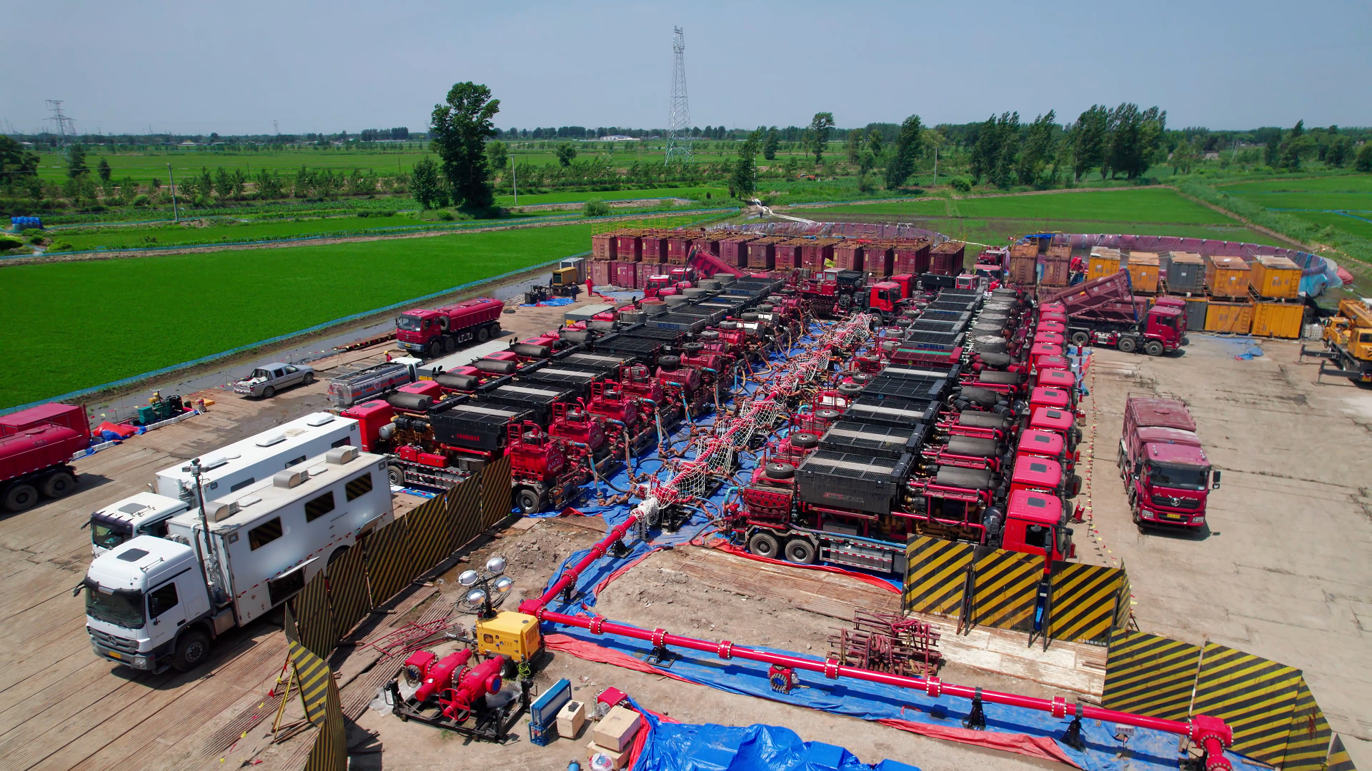

Product introduction of Discharge Pipeline
The discharge pipeline is an important connecting component in the high-pressure discharge system of the hydraulic end of the drilling mud pump. It is mainly used to transport the high-pressure drilling fluid discharged from the hydraulic end of the mud pump to the discharge main pipe, high-pressure manifold, air tank or subsequent well control and circulation systems.
When the mud pump is in operation, the piston reciprocates within the cylinder liner. After the discharge valve is opened, the high-pressure drilling fluid enters the discharge pipeline through the hydraulic end discharge port and is then transported to the subsequent high-pressure system. Therefore, the discharge pipeline is constantly subjected to internal high pressure, pressure pulsation, pipeline vibration, as well as the erosion and corrosion of drilling fluid.
The discharge pipeline is usually composed of straight pipe sections, elbows, tees, flanges, and other special high-pressure connection structures. The specific composition is determined according to the model of the slurry pump and the on-site pipeline layout. The discharge interfaces, pipe diameters, center distances, connection forms and pressure ratings of different pump types may vary. When purchasing, they should be matched according to the original equipment structure.
The main function of the discharge pipeline
1. Transporting high-pressure drilling fluid: The discharge pipeline is connected to the hydraulic end discharge port of the mud pump and the subsequent high-pressure system, forming a continuous high-pressure mud transportation channel.
2. Connect the hydraulic end to the discharge system: According to the structure of the equipment, the discharge pipeline can be connected to the discharge flange, discharge main pipe, discharge air tank, high-pressure manifold and other discharge side equipment.
3. Adapt to the spatial layout of equipment: Through straight pipes, elbow pipes, tees and different connection end structures, the discharge pipeline realizes the position transition and direction change between the hydraulic end discharge outlet and the on-site high-pressure manifold.
4. Bearing pressure and pipeline loads: In addition to withstanding the internal medium pressure, the discharge pipeline also needs to withstand periodic pressure pulsation, pipeline vibration, and additional loads caused by installation deviations.
The high-pressure discharge working process
When the piston of the mud pump enters the discharge stroke, the pressure in the working chamber rises. Under the action of the pressure difference, the discharge valve opens, and the drilling fluid flows through the valve seat flow channel into the hydraulic end discharge channel, and then enters the discharge pipeline.
The discharge pipeline continues to transport the high-pressure slurry to the main discharge pipe and subsequent systems. Due to the periodic discharge flow of reciprocating pumps, there will be obvious pressure and flow pulsations in the pipeline. Therefore, the discharge system is usually equipped with an discharge air tank or other pulsation buffer devices.
The discharge pipeline itself is not used to eliminate pulsation. Its main task is to safely and stably convey high-pressure media. Pulsation control is mainly accomplished by dedicated devices such as the air discharge bag.
The difference between the discharge flange and the discharge main pipe
Discharge pipeline: It is a high-pressure conveying connection system on the discharge side of the hydraulic end, which can include one or more sections of straight pipes, elbow pipes and connecting fittings.
Discharge flange: It is a rigid connection component at the discharge interface position, mainly providing mechanical connection, flow channel alignment and sealing installation foundation.
Discharge main pipe: It is usually used to collect high-pressure fluids from multiple hydraulic end discharge outlets and then uniformly transport them to the subsequent system.
The three components cooperate with each other in the discharge system, but they have different structures and functions. Therefore, they cannot be treated as the same part merely as "discharge pipe" or "discharge interface".
The relationship with the discharge of the air bag
Mud pumps belong to reciprocating positive displacement pumps, and there will be periodic fluctuations in flow and pressure on the discharge side. The discharge pipeline is responsible for transporting high-pressure slurry, while the discharge air tank is mainly used to absorb part of the pressure pulsation and reduce the impact and vibration on the high-pressure pipeline and related connecting parts.
Both should be matched in accordance with the original equipment pipeline layout. The installation position, interface size and connection direction of the air discharge package may all affect the length, bending Angle and interface position of the discharge pipeline.
Pipe diameter and internal flow channel
The inner diameter of the discharge pipeline is an important selection parameter. The pipe diameter should be matched with the discharge flow rate of the slurry pump, the discharge outlet of the original equipment and the subsequent manifold interface to avoid obvious sudden diameter reduction, misalignment or discontinuity of local flow channels.
Unreasonable internal steps and sharp turns may increase local flow resistance and at the same time subject elbows, tees and other positions to stronger mud erosion. Therefore, when selecting the model, in addition to checking the interface size, attention should also be paid to the internal flow channel structure and the alignment after connection.
Connection form and sealing
The discharge pipeline can be connected by flange, oil thread, thread or other special high-pressure connection methods according to the design of the slurry pump. Each connection structure has corresponding sealing parts and assembly requirements. It is not possible to determine whether they can be interchanged merely based on the nominal diameter.
For flange connection structures, the outer diameter, thickness, number of bolt holes, hole diameter, hole spacing and sealing surface or sealing groove of the flange should be checked. For the oil-screw connection structure, the oil-screw model, connection dimensions and the matching sealing form should be confirmed.
If the interface leaks repeatedly, the sealing parts, sealing surfaces, connection alignment and pipeline support conditions should be inspected. Pipeline misalignment should not be compensated for by continuously increasing the tightening force.
Pressure pulsation, vibration and pipeline support
The discharge side of the mud pump is constantly subjected to strong pressure pulsation and mechanical vibration. Therefore, the support and alignment of the discharge pipeline are of great significance.
If the pipeline support is insufficient or the pipeline with deviation is forcibly straightened by flange bolts during installation, additional stress may be formed in the discharge flange, elbow, tee or welding transition area.
Long-term cyclic loading may lead to loose connections, seal failure, local wear and even structural fatigue. During installation, natural centering should be maintained, and necessary pipeline supports and fixed structures should be set up in accordance with the original equipment requirements.
Erosion and wear inspection
Solid particles may be present in the drilling fluid, which can erode the inner wall when passing through the discharge pipeline at high speed. The outer side of the elbow, the position of the three-way diverter, the internal steps and the parts with sudden changes in flow direction usually need to be inspected with emphasis.
When conducting maintenance on the discharge pipeline, attention should be paid to thinning of the inner wall, local erosion pits, corrosion, cracks, abnormal welds, damage to the connection surface and external deformation.
For internal areas that cannot be directly observed, corresponding inspection methods should be adopted in accordance with the on-site maintenance system and the original equipment requirements to determine whether the remaining state of the pipe wall meets the requirements for continued use.
Key points for selection
When purchasing the discharge pipeline of a drilling mud pump, it is recommended to focus on confirming the following information:
1. Brand, series and specific model of mud pump;
2. Hydraulic end and discharge interface model;
3. The specific installation position and layout direction of the discharge pipeline;
4. Inner diameter and outer diameter of the pipeline;
5. Length of straight pipe section;
6. Elbow Angle and bending direction;
7. Three-way or branch pipe structure, if any;
8. Connection form at both ends;
9. Flange specifications, hole positions and sealing surface structure, if flanges are used;
10. Oil nonyl model and matching seals, if oil nonyl is adopted;
11. Installation center distance and spatial direction;
12. Interface relationship with the main discharge pipe, the air discharge tank and the high-pressure manifold;
13. Work pressure grade;
14. Original part number, physical sample or technical drawing.
Installation and Maintenance
Before installing the discharge pipeline, it should be confirmed that the interior is clean and free of welding slag, sand particles, metal shavings or other foreign objects, to prevent foreign objects from entering the hydraulic end or the subsequent high-pressure system.
When connecting the hydraulic end, the main discharge pipe and the high-pressure manifold, the interfaces should be kept naturally centered. Do not use flange bolts or oil bolts to forcibly straighten the obviously misaligned pipelines.
Before installing flange seals or oil seals, it is necessary to check whether there is erosion, scratches or corrosion on the sealing surface and confirm that the specifications of the seals are correct.
During the operation of the mud pump, regular checks should be conducted on pipeline vibration, interface leakage, loose supports and local erosion. Before disassembling any components of the discharge pipeline, it is necessary to confirm that the mud pump has been shut down and the entire high-pressure discharge system has been completely depressified.
Procurement Instructions
Juli Petroleum Drilling and Production Equipment Co., Ltd. provides accessories for discharge pipelines and high-pressure discharge systems of drilling mud pumps. The discharge pipeline is mainly used to connect the hydraulic end discharge outlet with the discharge main pipe, the discharge air tank and the subsequent high-pressure manifold, undertaking the function of high-pressure drilling fluid transportation and pipeline connection. The selection and matching can be carried out based on the model of the mud pump, the discharge interface, the pipe diameter, length, the bending direction, the connection form, the pressure rating, the original part number and the technical drawings.