



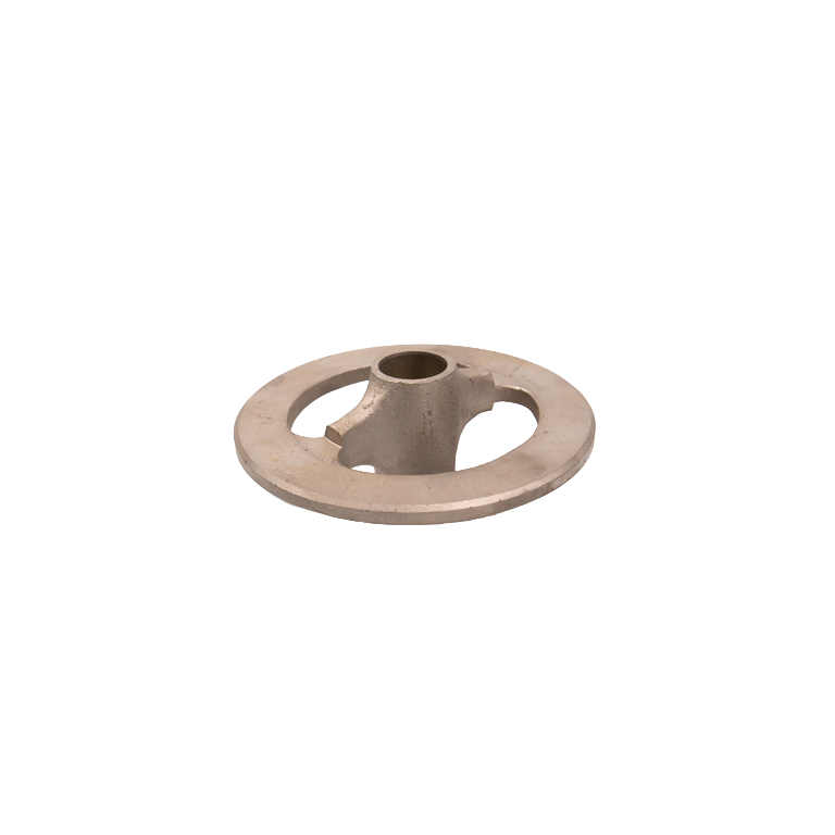
Product Introduction of Valve Stem Guide
The valve stem guide is a guiding and positioning accessory in the hydraulic end valve group of the drilling mud pump. It is mainly used in conjunction with the valve body, valve stem, valve spring, valve seat and related supporting parts. It is used to limit the lateral offset of the valve stem or valve body during the opening and closing process and keep the valve components moving stably in the specified direction.
During the operation of the drilling mud pump, the suction valve and the discharge valve need to be frequently opened and closed under the action of pressure difference. The valve stem guide cooperates with the valve stem through the internal guide hole or guide bushing, helping the valve body maintain the correct center position, reducing abnormal swing and skew, and providing guiding conditions for the correct contact between the valve body and the valve seat after the valve body falls back.
Different mud pumps and hydraulic end structures may adopt upper valve stem guides, lower valve stem guides or other dedicated guiding structures. The shape, installation method, valve stem fit dimensions, and the fit relationship with the spring, valve cover or cylinder may vary at each position. Accurate selection should be made based on the original part number and technical drawings.
The main function of the valve stem guide
1. Valve stem movement guidance: Radial constraints are imposed on the opening and closing movements of the valve stem or valve body to reduce the lateral swing and offset of the valve components during operation.
2. Maintain the center position of the valve body: Keep the movement center of the valve body as consistent as possible with the center of the valve seat, which is conducive to the correct landing of the valve body on the sealing surface of the valve seat when it is closed.
3. Stabilize the movement of the valve group: Under the high-speed reciprocating working conditions of the mud pump, it helps the valve body maintain a relatively stable opening and returning trajectory, reducing abnormal inclination, eccentric wear and impact.
4. Positioning in coordination with springs and valve groups: Depending on the specific hydraulic end design, the valve stem guide may also work together with the valve spring, valve cover, support parts or the internal structure of the hydraulic cylinder to complete the installation and positioning of the valve group.
Working principle
When a corresponding pressure difference is formed between the working chamber of the mud pump and the suction side or discharge side, the valve body overcomes the spring force and other resistances to generate an opening movement. The valve stem moves axially within the guide hole or guide bushing of the valve stem guide, and the guide restricts its radial displacement, thereby controlling the movement direction of the valve body.
When the pressure conditions change, the valve spring pushes the valve body back to its original position, and the valve stem guide continues to maintain the movement center of the valve body, enabling the valve body to fall back to the valve seat position more accurately.
The valve stem guide itself is not the main sealing component of the valve assembly. The true closing seal of the valve is mainly accomplished by the contact pair between the valve body and the valve seat. The function of the guide is to help the valve body maintain the correct movement and positioning state.
Upper valve stem guide and lower valve stem guide
Some drilling mud pumps adopt valve stem guiding structures at different positions at the top and bottom at the hydraulic end. Although both have guiding functions, their installation positions and matching parts may be different.
Upper valve stem guide: Installed on the upper part of the valve assembly in some structures, it can be used in conjunction with the valve spring, valve cover or corresponding support components to guide and position the movement of the upper part of the valve body.
Lower valve stem guide: In some structures, it is used in coordination with the internal installation position of the liquid cylinder and the lower structure of the valve group to fix and guide the movement of the valve components.
The upper and lower guides usually cannot be directly interchanged just because the sizes of the guide holes are close. When making a purchase, the installation position, part number and hydraulic end structure should be clearly defined.
Guide hole and fit clearance
The guide hole or internal guide bushing of the valve stem guide is a key working part. Its size needs to be correctly matched with the outer diameter of the valve stem. It is necessary to ensure that the valve stem can move smoothly axially without losing its effective guiding function due to excessive clearance.
As the operating time increases, the guide holes or guide bushings may wear out, resulting in an increase in the radial clearance of the valve stem. When the clearance is too large, the valve body may experience obvious swinging or skewing, and further cause abnormal wear of the valve stem, valve seat and related parts.
Some mud pump maintenance data have specific regulations on the allowable clearance between the valve stem and the guide vane. Therefore, the actual wear limit should be carried out in accordance with the corresponding pump type maintenance manual and should not be replaced by a uniform value.
Guide bushing structure
Some mud pump valve stem guide devices adopt a replaceable guide bushing structure. The main body of the guide device is responsible for installation and support, and the internal bushing directly forms a motion fit with the valve stem.
When the bushing wear reaches the repair limit, it can be replaced according to the original equipment maintenance requirements, without necessarily having to replace the guide vane as a whole. Whether to adopt an independent bushing, as well as the material and installation method of the bushing, should be determined based on the specific structure of the mud pump.
Common Failures and Inspections
Common abnormalities of valve stem guides include wear of guide holes, wear or loosening of guide bushings, mud erosion, corrosion, local deformation, damage to the installation surface, and cracks in the main body, etc.
During maintenance, special attention should be paid to checking the inner diameter of the guide hole, the fit clearance between the valve stem and the guide hole, the installation status of the bushing, and the installation positioning surface of the guide.
If it is found that the valve body is unevenly worn, the valve stem is worn on one side, the valve seat contact is abnormal or the valve group movement is unstable, in addition to checking the valve body, valve seat and spring, it is also necessary to check whether the valve stem guide is worn or eccentric.
Key points for selection
When purchasing the valve stem guide for drilling mud pumps, it is recommended to focus on confirming the following information:
1. Brand, series and specific model of mud pump;
2. Hydraulic end or hydraulic cylinder model;
3. Installation position of the suction valve or discharge valve;
4. Upper guide or lower guide type;
5. Specifications of the matching valve body and valve stem;
6. Inner diameter of the guide hole and mating dimensions;
7. Outer diameter, total height and installation dimensions of the guide device;
8. Whether replaceable guide bushings are adopted inside;
9. The mating structure with valve springs, valve covers or hydraulic cylinders;
10. Positioning steps, installation holes or fixed structures;
11. Original part number, physical sample or technical drawing.
Installation and Maintenance
Before installation, the valve stem guide, guide hole or guide bushing and the adjacent installation position of the liquid cylinder should be cleaned, and mud deposits, metal particles and other foreign objects should be removed.
After installation, it should be confirmed that the guide has been correctly positioned, and the valve stem can move smoothly axially in the guide hole without obvious jamming, abnormal skew or excessive radial wobbly.
If an independent guide bushing is adopted, when replacing the bushing, it should be installed in accordance with the corresponding slurry pump maintenance process to avoid deformation of the bushing or out-of-roundness of the guide hole during the press-fitting process.
Before overhauling the valve stem guide, the pump should be stopped, isolated and it should be confirmed that the pressure at the hydraulic end has been completely released in accordance with the equipment operation procedures. Then, the valve cover and related valve assembly components can be disassembled.
Procurement Instructions
Juli Petroleum Drilling and Production Equipment Co., Ltd. provides valve stem guides and hydraulic end valve group accessories for drilling mud pumps. The valve stem guide is mainly used for guiding, centering and stabilizing the movement of the valve stem and valve body during opening and closing. Different pump types vary in terms of upper and lower installation positions, guide hole sizes, bushing structures, shapes and fixing methods. When making a purchase, it is recommended to provide the model of the mud pump, the model of the hydraulic end, the installation position, the size of the valve stem, the original part number, physical samples or technical drawings for matching verification.